](https://file-host.link/website/marseng-ky42u0/assets/blog-images/4c64dddb-4a99-4573-a604-4beaae37a7bb/1776784047738867_f4a47c3f97c04886bfe9659d39390384/360.webp)
Introduction
A turbine blade machined 0.0005 inches out of spec doesn't just underperform — it can initiate fatigue cracking under thermal cycling that grounds an aircraft. Turbine blades, hydraulic valves, and flight control actuators operate under extreme temperatures, pressure differentials, and vibration loads where even minor dimensional deviation causes fatigue cracking, internal leakage, or aerodynamic efficiency loss.
Many machine shops claim "precision machining," but consistent micron-level tolerances in aerospace require a specific combination of machine capability, process control, tooling, and environmental management. Most sourcing mistakes only surface when parts fail qualification or cause assembly issues downstream.
Understanding how CNC machining actually holds these tolerances is what separates capable suppliers from expensive dead ends.
This guide breaks down exactly how CNC machining achieves and maintains micron tolerances for aerospace parts, from programming and fixturing through final inspection.
Key Takeaways
- Micron tolerances (±1–10 µm) prevent structural failure and performance loss in aerospace assemblies
- CNC machining achieves these tolerances through precise programming, rigid machine structures, advanced tooling, and real-time feedback
- Thermal expansion, tool wear, and material hardness threaten consistency and must be actively controlled
- Inspection requires CMMs, vision systems, and temperature-stabilized environments
- Process discipline, in-house tooling, and a traceable quality system distinguish shops that can deliver from those that cannot
What Are Micron Tolerances in Aerospace CNC Machining?
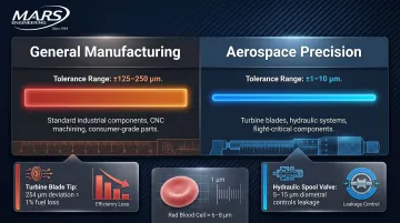
A micron tolerance is measured at a scale almost invisible to the naked eye. One micron (1 µm) equals 0.000039 inches—smaller than a single red blood cell. Aerospace tolerances typically range from ±1 µm to ±25 µm depending on component criticality, compared to ±125–250 µm in general manufacturing.
Micron tolerances represent a fundamentally different category of manufacturing. Achieving ±10 µm requires controlled thermal environments, purpose-built metrology equipment, and process qualification protocols — not simply more experienced operators. A part held to ±10 µm will perform under extreme aerospace conditions; one held to ±100 µm risks failing qualification testing before it ever sees service.
Why aerospace specifically requires this level of precision:
Aerospace components operate under conditions that amplify the consequences of dimensional error:
- Extreme temperature swings cause materials to expand and contract
- High-pressure differentials exploit even microscopic gaps in sealing surfaces
- Vibration loads over thousands of flight hours propagate stress from geometric imperfections
- Long service cycles mean small deviations compound into critical failures over time
For example, a 0.010-inch (254 µm) tip clearance deviation in high-pressure turbine blades results in approximately 1% specific fuel consumption loss and 10°C exhaust gas temperature margin deterioration. In hydraulic spool valves, diametral clearances of 5–15 µm between spool and bore control internal fluid leakage—any dimensional drift beyond that band causes loss of actuation control.
These aren't edge cases — they're the dimensional thresholds that separate a flight-ready component from a rejected one. Aerospace procurement teams evaluating suppliers need documented process capability data (Cpk values, gage R&R studies, measurement traceability) that demonstrates repeatable performance at the micron level, not just sample parts that passed inspection.
How CNC Machining Achieves Micron-Level Tolerances
Micron-level tolerances require programming, fixturing, cutting, and monitoring to work in coordination. A failure in any one stage propagates through to final dimensions, consuming the entire tolerance band.
Programming and Setup
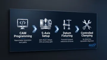
CAM programming defines tool paths at sub-micron resolution, setting feed rates, depths of cut, and approach angles that minimize deflection and vibration. FANUC nano-interpolation calculates motion commands with nanometer (10⁻⁹ m) precision, executing them via a digital servo system to achieve submicron surface finishes.
Multi-axis CNC machines allow complex geometry to be machined in a single setup, eliminating re-fixturing errors that would otherwise consume tolerance budget. Adding 5-axis capability reduces setups by 60% and increases process accuracy by 25%. For aerospace buyers, this means fewer opportunities for dimensional stack-up and tighter control over geometric relationships between features.
Fixturing and workholding contribute directly to achievable tolerances. Any movement, flex, or inconsistency in how the part is held introduces dimensional error. Aerospace-grade fixturing controls this through:
- Precision-ground datums that establish repeatable reference surfaces
- Controlled clamping forces that stabilize the part without inducing distortion
- Part and table indexers that enable 360-degree rotation without removing the workpiece
At M.A.R.'s Engineering, 4-axis CNC mills equipped with these indexers preserve alignment between critical surfaces throughout the cut, eliminating handling-induced errors between setups.
Cutting, Grinding, and Finishing
CNC turning and milling get parts close to final dimension, but grinding—particularly centerless grinding—achieves the final precision pass. Centerless grinding can achieve tolerances of ±2.5 µm (±0.0001 inches) and surface finishes of Ra 0.4 µm, specifications that milling alone cannot reach consistently.
Shops with in-house centerless grinding capability can hold the tightest aerospace specifications without outsourcing the finishing step. M.A.R.'s Engineering operates six centerless grinders that achieve finishes up to 4 microinches and tolerances to 0.0001 inches on materials ranging from aluminum to hardened steel, completing the full process chain in one facility.
Tooling quality matters more than buyers often realize. Worn or imprecise tooling directly degrades the tolerance achievable. Shops that manufacture custom tooling in-house using Wire EDM eliminate lead time delays and can produce tools precisely matched to the geometry being cut.
For aerospace work, this matters because specialty features and complex profiles frequently require custom cutting tools. Waiting weeks for an off-the-shelf approximation isn't an option when tolerances are measured in microns.
In-Process Monitoring and Control
Modern CNC machines use closed-loop feedback systems—encoders, probes, and in-process gauging—to monitor actual part dimensions during machining and automatically apply corrections before the cut is completed. In-machine probing systems deliver measuring repeatability of 0.8 µm, preventing tolerance drift from accumulating across a production run.
Thermal compensation is a critical control mechanism that many buyers underestimate. CNC machines generate heat during operation, causing spindles, ball screws, and workpieces to expand. Active AI thermal displacement compensation reduces Z-axis drift from 25.8 µm down to 6.1 µm. Without this, thermal drift alone can consume the entire tolerance band on a tight aerospace feature.
The Key Challenges That Make Micron Tolerances Difficult to Achieve
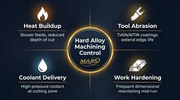
Material Hardness and Machinability
Aerospace alloys like titanium, Inconel, and hardened tool steels resist cutting forces and generate significant heat at the tool-workpiece interface. Titanium alloys (Ti-6Al-4V) exhibit low thermal conductivity, limiting heat dissipation and resulting in rapid tool wear and work hardening. Inconel 718 machining is dominated by abrasion and adhesion wear mechanisms, particularly with ceramic inserts that show greater tendency for notch wear.
Managing these materials requires a deliberate response to each failure mode:
- Slower feed rates and reduced depths of cut to limit heat buildup
- Specialized tool coatings (TiAlN, AlTiN) to extend edge life under abrasion
- High-pressure coolant delivery directed precisely at the cutting zone
- Frequent monitoring for work hardening, which can shift dimensions mid-run
Tool Wear as a Compounding Problem
In a production run, the first part and the hundredth part see different tool geometries as the cutting edge degrades. This means dimensional accuracy shifts over time unless actively managed. Shops addressing this challenge implement:
- Scheduled tool change intervals based on material and cutting parameters
- In-process gauging feedback to detect drift before it exceeds tolerance
- Operator protocols for offset adjustments mid-run
- Tool wear compensation algorithms in CNC programming
M.A.R.'s Engineering uses a three-stage production monitoring approach where operators separate parts into batches of 5-25 pieces and verify dimensions before approving each batch, catching tool wear drift before it propagates across the entire production run.
Environmental Factors: Temperature and Vibration
A 1°C change in ambient temperature can cause a steel workpiece or machine structure to expand or contract by several microns. Consider these thermal expansion rates:
- Ti-6Al-4V: 8.60 µm/m-°C — a 100 mm feature expands 0.86 µm per 1°C
- Inconel 718: 13.0 µm/m-°C — a 100 mm feature expands 1.30 µm per 1°C
- 440C Stainless Steel: 10.2 µm/m-°C — a 100 mm feature expands 1.02 µm per 1°C
- Aluminum 7075-T6: 23.6 µm/m-°C — a 100 mm feature expands 2.36 µm per 1°C
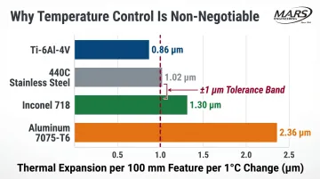
Shops that hold the tightest tolerances control the temperature of their machining environment, their inspection room, and allow parts to thermally stabilize before measurement. ISO 1:2022 fixes the standard reference temperature at exactly 20°C, and measuring systems operating at different temperatures introduce additional measurement uncertainty.
Geometric Complexity and Deflection
Thin walls, deep bores, and small-diameter features flex under cutting forces, making it difficult to hold dimensions without specialized support strategies. For example, a thin-walled hydraulic sleeve with a critical bore diameter can deflect during machining if cutting parameters are too aggressive, causing the bore to measure out-of-tolerance even though the machine followed the programmed path perfectly.
Four approaches help control deflection in practice:
- Reduce cutting forces by dialing back feed rates and axial depths of cut
- Add support tooling or custom fixtures to stabilize thin sections during the cut
- Sequence material removal to keep the part balanced as stock is cleared
- Finish with light passes — minimal cutting pressure, maximum dimensional control
Aerospace Components That Demand Micron-Level Precision
Turbine Engine Components
Blade tip clearances affect engine efficiency and surge margin. Even small deviations multiply across hundreds of blades, creating measurable performance loss. Active Clearance Control (ACC) sensors require accuracy on the order of 25.4 µm (0.001 inches) to function properly.
Hydraulic Spool and Sleeve Valves
Internal leakage is controlled entirely by bore-to-spool fit, often held to 2–5 µm. High-pressure directional control valves require diametral clearances around 5 to 15 µm to control internal fluid leakage. Any dimensional deviation beyond this range causes loss of actuation control or excessive leakage, compromising hydraulic system performance.
M.A.R.'s Engineering produces hydraulic fittings, fluid connectors, and sleeves with outer diameter tolerances as close as 0.0001 inches, meeting the exacting requirements of aerospace hydraulic systems.
Flight Control Actuators
Dimensional precision determines response linearity and prevents binding under load. Actuator bores, splines, and mating surfaces must maintain micron-level tolerances across temperature extremes and thousands of flight cycles.
High-Volume Critical Components
High-volume components operate in the micron-tolerance range not because of complexity, but because small deviations multiply across hundreds of assemblies. Even straightforward parts carry serious reliability consequences:
- Fasteners that maintain structural load paths across airframe joints
- Fuel injector orifices where bore diameter directly controls combustion timing
- Landing gear pivot pins where clearance determines fatigue life under cyclic loading
These components are typically made from 440C stainless steel, 52100 bearing steel, titanium alloys, or nickel superalloys — materials chosen for their performance in flight, and precisely the ones that are hardest to machine to tolerance. That combination is why not all machine shops are qualified for aerospace component production.
How Micron Tolerances Are Verified After Machining
Coordinate Measuring Machines (CMMs)
Inspection at the micron level requires equipment matched to that scale. CMMs use a sensitive probe with a light-contact tip to map part geometry automatically, eliminating operator handling variability and providing data on complex surfaces, GD&T features, and roundness that hand gauges cannot capture reliably.
High-precision CMMs deliver measurement errors as low as (0.35 + L/1000) µm with 0.01 µm resolution, but they must operate in controlled environments to maintain accuracy.
Vision Systems and Optical Comparators
Where probe contact would distort or damage fine features, vision systems and optical comparators offer a complementary approach — optically enlarging the part for dimensional measurement without touching it. Renishaw Equator gauging systems provide high-speed comparative gauging for shop-floor inspection with comparison uncertainty of ±2 µm, operating in temperatures from 5°C to 50°C.
Vision systems are well-suited for small, thin-walled, or fragile aerospace components where probe contact could alter the measurement.
Temperature Stabilization Before Inspection
Shops must bring parts to a controlled temperature environment and allow them to stabilize before measurement. Thermal expansion across the tolerance band can make a conforming part appear out of specification — or pass one that shouldn't.
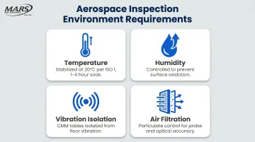
Aerospace-capable inspection environments typically control for:
- Temperature: Stabilized at 20°C (68°F) per ISO 1 standard, with soak times of 1–4 hours depending on part mass
- Humidity: Maintained to prevent surface oxidation on bare metal parts awaiting measurement
- Vibration isolation: CMM tables isolated from floor vibration to protect sub-micron measurement fidelity
- Air filtration: Particulate control to prevent debris from affecting probe contact or optical readings
Frequently Asked Questions
What is considered a micron tolerance in CNC machining?
A micron (1 µm) equals 0.000039 inches. Micron-level tolerances in CNC machining typically refer to features held within ±1 to ±10 µm—far tighter than the ±125–250 µm common in general manufacturing.
What CNC processes are used to achieve micron-level tolerances in aerospace?
Multi-axis CNC milling, CNC turning, and precision grinding (especially centerless grinding) are the primary processes, with Wire EDM used for tooling and fine features. A combination of processes, not a single operation, typically achieves the final tolerance.
How does thermal expansion affect CNC machining tolerances?
Temperature changes cause metals to expand or contract by several microns per degree, which can consume the entire tolerance band on tight aerospace features. Controlled machining environments and in-machine thermal compensation are required to manage this effect.
What aerospace parts require the tightest CNC machining tolerances?
Hydraulic spool valves, turbine blade tip clearances, fuel injector orifices, and flight control actuator bores routinely require tolerances of 2–5 µm or tighter to prevent leakage, performance loss, or binding.
How are micron-level tolerances verified after CNC machining?
CMMs, vision systems, and digital comparators are used in temperature-stabilized inspection environments. Parts must thermally stabilize before measurement to prevent thermal expansion from producing false readings.
What makes a machine shop qualified to produce aerospace parts to micron tolerances?
Qualification requires capable equipment, environmental controls, in-process inspection systems, ISO-compliant quality documentation, and demonstrated process consistency across production runs. M.A.R.'s Engineering meets these requirements through ISO compliance, Mil-I-45208A conformance, centerless grinding to 0.0001 inches, and in-house Wire EDM for custom tooling.