Introduction
When parts demand tolerances measured in ten-thousandths of an inch—where a human hair is roughly three times thicker than your entire tolerance band—standard turning methods often fall short. Deflection, vibration at the cutting point, and cumulative setup error all degrade dimensional accuracy, particularly on small-diameter, high-aspect-ratio components.
Swiss CNC machining addresses these problems directly. By supporting the workpiece within millimeters of the cutting zone and completing all operations in a single setup, Swiss-type lathes achieve tolerances that conventional turning cannot reliably hold.
This article covers the mechanical design principles behind Swiss CNC machining—specifically the sliding headstock and guide bushing—realistic tolerance ranges for production environments (±0.0001" to ±0.0005"), and which industries depend on this level of precision. You'll also find guidance on evaluating Swiss CNC capabilities and selecting the right machining partner.
TLDR
- Swiss CNC machining achieves production tolerances of ±0.0002" routinely, with ±0.0001" under controlled conditions
- Guide bushing support eliminates deflection on long, slender parts (L/D ratios above 3:1)
- Single-setup completion removes cumulative error from re-chucking and re-fixturing
- Best suited for small-diameter parts (up to ~1.25"), high volumes, and complex geometries
- Medical, aerospace, electronics, and automotive sectors demand Swiss-level precision for critical components
What Is Swiss CNC Machining?
Swiss CNC machining—also called Swiss turning or Swiss-type lathe machining—is a precision manufacturing process that uses a sliding headstock and guide bushing to produce small, complex parts with extremely tight tolerances. The process originated in Switzerland's 19th-century watchmaking industry, where watchmaker Jakob Schweizer developed a unique lathe in the 1870s to manufacture tiny, precise screws. Since then, the technology has expanded into medical, aerospace, electronics, automotive, and defense applications where dimensional variation directly affects functional performance.
The Mechanical Foundation: Sliding Headstock and Guide Bushing
Two defining mechanical elements distinguish Swiss CNC machining from conventional turning:
The sliding headstock moves bar stock axially through the machine along the Z-axis while cutting tools remain stationary. Rather than holding the workpiece fixed and moving the tool, the Swiss design feeds material through the machine continuously.
The guide bushing supports the workpiece immediately adjacent to the cutting zone—typically within 1-2 mm of the active cutting point. This fixed bushing delivers rigid support directly at the tool-to-workpiece interface, where it has the most effect on dimensional accuracy.
Swiss vs. Conventional: The Key Distinction
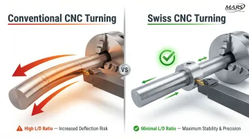
On a conventional lathe, the workpiece is clamped in a chuck and remains stationary while the tool travels along the length of the part. As the tool moves away from the chuck, the unsupported length of bar stock increases progressively, causing flex and vibration that degrade accuracy.
In Swiss turning, bar stock feeds through a fixed guide bushing while the headstock moves. The bushing provides continuous support at the cutting point throughout the entire operation. The result: reliable accuracy on long, slender parts—especially those with length-to-diameter ratios above 3:1, where conventional lathes struggle most.
How Swiss Turning Achieves Tight Tolerances
The Physics of Deflection
Conventional lathes suffer from cantilever deflection that increases with the cube of the unsupported length. As the cutting tool moves away from the chuck, each additional inch of unsupported bar stock exponentially increases the bending moment under cutting forces. For slender parts—particularly those with L/D ratios above 3:1—this deflection becomes the dominant source of dimensional error.
When cutting pressure is applied to an unsupported 4-inch length versus a 1-inch length of the same diameter, the deflection doesn't simply quadruple—it increases by a factor of 64 (4³). That exponential relationship is precisely why conventional turning cannot reliably hold tight tolerances on long, thin components—and why the guide bushing changes everything.
Guide Bushing Eliminates Unsupported Length
The guide bushing neutralizes this deflection problem entirely. Because it supports the workpiece within fractions of an inch of the active cutting zone at all times, the effective unsupported length is near zero regardless of total part length. Even when machining a 6-inch-long component, the cutting forces act on a section supported as if it were only 2 millimeters long.
That constant, rigid support maintains consistent tool-to-workpiece contact geometry throughout the entire cut, preventing the vibration and flex that degrade surface finish and dimensional accuracy on conventional equipment.
Single-Setup Machining Eliminates Cumulative Error
When turning, milling, drilling, and threading are completed in a single setup without re-chucking, cumulative error from multiple setups is eliminated. Each transfer or re-fixturing introduces re-alignment tolerances that compound through the manufacturing sequence. A part requiring five setups might accumulate 0.0005" of error from re-chucking alone, even before accounting for machining variation.
Single-setup completion removes this error source entirely. The relationship between features—cross-hole position relative to turned diameter, thread location relative to datum surfaces—remains fixed by the machine's coordinate system rather than being subject to fixture repeatability.
Thermal Stability and Real-Time Compensation
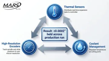
Modern Swiss CNC machines maintain micron-level accuracy during long production runs through active thermal compensation. Three systems work in concert to prevent temperature-induced drift:
- Thermal sensors distributed throughout the machine feed real-time expansion data to the controller, which automatically applies tool position offsets to compensate for dimensional shift
- High-resolution encoders track actual spindle and slide positions with sub-micron resolution
- Coolant management systems regulate temperature directly at the cutting zone
As machines warm up during production, these systems adjust tool offsets in real time to hold dimensional targets—maintaining 0.0002" tolerances across hours of continuous operation.
Consistent Bar Feeding Under Controlled Tension
Automatic bar feeders enable continuous, consistent feeding of bar stock at controlled tension and feed rates. Inconsistent bar feed pressure directly contributes to diameter variation: if feeding pressure varies, the bar position relative to the guide bushing shifts slightly, altering the effective cutting geometry.
Well-designed feed systems minimize this variable, maintaining constant tension throughout the production run. Precision centerless ground bar stock is typically required, held to ±0.0005" diameter consistency, to ensure a proper fit through the guide bushing and maintain diameter uniformity from one part to the next.
Understanding Swiss CNC Tolerance Ranges
Standard vs. Best-Case Production Tolerances
Swiss-type lathes routinely hold tolerances of ±0.0002" (±5 microns) in production environments, with best-case capability reaching ±0.0001" (±2.5 microns) under controlled conditions. However, these figures represent different scenarios: the ±0.0002" figure describes what can be reliably maintained across production runs of 1,000+ parts with standard process control, while the ±0.0001" capability requires optimal material, ideal geometry, frequent tool changes, and 100% inspection.
Achievable tolerance is not a single number but a function of several interacting variables.
Variables That Affect Tolerance Capability
Five variables drive tolerance capability on any Swiss job:
- Material machinability — Free-machining alloys (brass, aluminum 6061, 303 stainless) hold tighter tolerances than gummy materials like titanium or engineering plastics; hardness, thermal expansion, and chip formation all play a role
- Length-to-diameter ratio — Swiss machining handles L/D ratios up to 20:1 via guide bushing support, where conventional turning struggles past 4:1
- Feature complexity — Turned diameters hold tighter than cross-drilled holes, milled flats, or threaded sections; each added operation contributes a small increment of variation
- Surface finish target — Ra 8 µin requires slower feeds and sharper tooling than Ra 32 µin; the parameters that optimize finish don't always optimize dimensional tolerance
- Production volume — Low-volume runs allow frequent inspection and offset adjustments; high-volume runs depend on SPC and predictable tool wear patterns
Dimensional, Geometric, and Positional Tolerances
Swiss CNC machining controls three distinct tolerance types simultaneously:
Dimensional tolerances govern size — turned diameters, groove depths, shoulder lengths — and typically appear as ±0.0002" on precision drawings.
Geometric tolerances control form (straightness, roundness, cylindricity, flatness). Swiss machines hold cylindricity within 0.0002" because the guide bushing eliminates the whipping that causes out-of-round conditions on conventional lathes.
Positional tolerances define feature relationships — hole location, datum alignment, true position. GD&T callouts like true position within Ø0.001" or perpendicularity within 0.0002" are well within Swiss capability, since all features are machined from a single setup and common coordinate system.
Material Choice and Tolerance: A Practical Matrix
Different materials respond differently to Swiss machining, affecting the practical tolerance floor:
| Material | Best Achievable Tolerance (OD) | Machining Challenge |
|---|---|---|
| Brass (C360) | ±0.003 mm (±0.00012") | Excellent machinability; surface finish can vary |
| Aluminum 6061-T6 | ±0.004 mm (±0.00016") | Stringy chips; burr formation |
| 303/304 Stainless | ±0.005 mm (±0.0002") | Work hardening; built-up edge on tooling |
| 17-4 PH Stainless | ±0.008 mm (±0.0003") | Abrasive; rapid tool wear |
| PEEK (Plastic) | ±0.010 mm (±0.0004") | Thermal expansion; moisture absorption |
| Inconel 718 / Titanium | ±0.012 mm (±0.0005") | Work hardening; excessive heat generation |
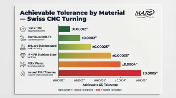
Source: Yuey Precision tight tolerance machining guide
Free-machining alloys consistently hit the tightest end of the tolerance range, while superalloys and plastics introduce thermal and wear challenges that widen the achievable band.
In-House Tooling and Tolerance Control
Shops with in-house tool-making capability can correct systematic errors by adjusting tooling geometry rather than accepting scrap. That in-house loop — identify error, modify tooling, verify, continue — is what separates shops that consistently hit ±0.0001" from those that accept drift as unavoidable.
M.A.R.'s Engineering's in-house Wire EDM produces custom tooling with next to no lead time. When a form tool is causing a consistent 0.0002" error in a specific feature, the EDM can modify that geometry within hours rather than waiting days for an external supplier — keeping production on schedule while correcting the dimensional drift at its source.
Verification: In-Process Gauging and SPC
Tolerance capability is verified through layered inspection systems. In-process gauging — using touch probes, air gauges, or contact measurement — provides real-time feedback during production, allowing automatic tool offset adjustments as cutting edges wear. In-process probing systems offer repeatability down to 0.00025 mm, enabling closed-loop correction before parts drift out of specification.
Statistical Process Control (SPC) tracks dimensional trends across production runs, catching systematic drift before it generates scrap. Key outputs from an ISO-compliant inspection system include:
- Full dimensional traceability tied to each production lot
- Trend data identifying tool wear patterns before tolerance limits are breached
- Auditable records retained post-production — required in aerospace, medical, and defense supply chains
Swiss CNC vs. Conventional CNC Turning: Precision Compared
Direct Comparison Across Three Dimensions
| Dimension | Swiss CNC Turning | Conventional CNC Turning |
|---|---|---|
| Achievable tolerance | ±0.0001" to ±0.0002" on small-diameter parts | ±0.001" to ±0.005" on comparable parts — a five- to ten-fold gap driven by guide bushing support and single-setup completion |
| L/D ratio stability | Stable up to 30:1 | Struggles beyond 4:1; at 10:1 (e.g., 0.25" dia. × 2.5" long), requires tailstocks or steady rests and still may not hold 0.0005" |
| Setup-induced error | Single setup eliminates re-chucking error entirely | Each transfer (rough turn → finish turn → mill flats → cross-holes) adds 0.0002"–0.0005" of positional error that compounds |
When Conventional Turning Still Makes Sense
Swiss machining is not universally superior. Conventional CNC turning remains appropriate for:
- Larger-diameter parts (typically above 1.25" diameter): Most Swiss machines accept bar stock up to 32-38 mm diameter, while conventional lathes handle 6" diameter and larger
- Short, stocky geometries where L/D is below 3:1 and deflection is not a concern
- Very low-volume or one-off prototypes where Swiss setup complexity and specialized bar stock requirements aren't justified
- Parts requiring large material removal where conventional machines offer greater rigidity and horsepower
Economic Crossover: Total Cost Per Part
Swiss-type lathes require 40-60% higher initial capital investment than conventional lathes—$150,000 to $500,000+ versus $50,000 to $300,000. However, they reduce cycle times by 30-70% on complex parts by consolidating operations. A part requiring 8 minutes of machining time across three setups on conventional equipment might complete in 3 minutes in a single Swiss setup.
At low volumes (under 500 parts), the higher machine cost and setup complexity favor conventional turning. As volume scales, reduced cycle time, eliminated secondary operations, and lower scrap rates on Swiss machines offset the capital difference. The crossover point falls between 500 and 1,000 parts, depending on part complexity and tolerance requirements.
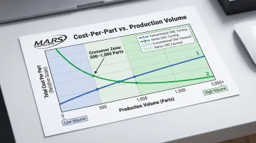
The real evaluation is total cost per part: machine cost amortized across volume, plus labor (setup and cycle time), plus scrap rate, plus secondary operations. Swiss machining wins decisively at high volume with tight tolerances; conventional turning wins at low volume with relaxed requirements.
Surface Finish and Micro-Finish Capabilities in Swiss CNC Machining
As-Turned Surface Finish Standards
Surface finish is measured using Ra (average roughness), the arithmetic average of surface height deviations from the mean line. Swiss CNC machining with proper tooling and cutting parameters achieves Ra values in the range of 8-32 µin (0.2-0.8 µm) straight from the machine. This represents a high-quality finish suitable for many precision applications without secondary processing.
Achieving finer finishes requires optimized cutting geometry, sharp carbide or ceramic inserts, and controlled feed rates. Slower feeds produce finer finishes but increase cycle time—a tradeoff managed based on application requirements.
Application-Specific Finish Requirements
Different industries demand different Ra targets:
- Medical implants: Articulating surfaces in orthopedic implants require mirror finishes with Ra < 0.02 µm, while bone-contacting surfaces may be intentionally roughened to promote osseointegration
- Fluid sealing components: Fluid sealing components: Ra 8-16 µin is the standard range for dynamic seals — fine enough to minimize friction, but not so smooth it strips away the lubricant film
- Aerospace fuel systems: Internal passages often call for Ra 32-63 µin, balancing flow characteristics against manufacturing cost
- Decorative or wear surfaces: Custom Ra targets apply here, driven by appearance requirements or friction/wear behavior under load
When those targets push beyond what standard turning delivers, post-machining operations close the gap.
Extending Finish Capability Through Post-Machining
When surface finish requirements exceed as-turned capabilities, secondary operations refine the result. Centerless grinding achieves surface finishes down to Ra 4 µin (0.1 µm) and finer, bringing turned parts to final precision finish.
M.A.R.'s Engineering runs centerless grinding in-house, reaching finishes to 4 µin and tolerances to 0.0001". Parts go from turning to final specification without leaving the facility — no hand-off delays, no risk of dimensional change during transfer.
Honing and polishing push finishes finer still. These processes suit applications like hydraulic valve bores or surgical instrument channels, where surface texture directly affects fluid control or biocompatibility.
Industries and Applications That Demand Swiss-Level Precision
Medical Devices: Where Dimensional Variation Affects Patient Outcomes
The medical device sector depends heavily on Swiss machining for components where dimensional variation directly affects patient outcomes. Orthopedic bone screws must maintain precise thread pitch and core diameter to achieve specified pull-out strength without fracturing bone. Surgical instrument shafts require tight straightness and cylindricity tolerances to function properly within narrow anatomical passages. Dental implants demand precise thread geometry to ensure proper osseointegration and long-term stability.
Swiss machining handles medical-grade stainless steel (316L), titanium alloys (Ti-6Al-4V), and cobalt-chrome while maintaining biocompatibility and achieving the dimensional precision these applications require.
Aerospace: Components Subject to Extreme Conditions
Aerospace manufacturing relies on Swiss machining for fuel system components, hydraulic fittings, electrical connectors, and precision fasteners. These parts face extreme pressure, vibration, and temperature cycling, making dimensional consistency critical to airworthiness. A fuel injector nozzle with dimensions outside specification may cause combustion instability; a hydraulic fitting with improper thread geometry may leak under pressure.
Aerospace qualification programs — including AS9100 and NADCAP — require documented process control and full material traceability, both of which Swiss machining operations are well-positioned to support.
Electronics: Signal Integrity Depends on Fit Tolerance
Electronics manufacturing uses Swiss-machined connector pins, contact probes, terminal blocks, and miniature housings where dimensional variation affects electrical performance. Contact resistance, signal integrity, and mechanical retention all depend on precise fit between mating components. A connector pin with diameter variation of 0.001" may cause intermittent contact or excessive insertion force.
High-volume production of these components—often in runs of 10,000+ units—benefits from Swiss machining's combination of tight tolerances and fast cycle times.
Automotive: High-Volume Precision for Fuel, Transmission, and Sensor Systems
Automotive systems apply Swiss machining to fuel injector components, transmission pins, valve guides, and sensor housings. These applications demand concentric stability and high-volume consistency: annual production volumes often exceed 100,000 units per part number, and dimensional drift during production results in costly scrap or field failures.
Swiss machining maintains 0.0002" tolerances across extended production runs through tool wear compensation and in-process monitoring — keeping scrap rates low even at automotive production volumes.
The Common Thread: Small Parts, Tight Tolerances, High Volume
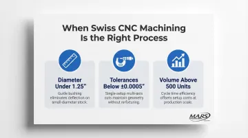
The combination of small part size, tight tolerances, and high production volume defines Swiss CNC applications. When a part design exhibits all three of the following, Swiss machining is almost always the right process:
- Diameter under 1.25" — bar-fed guide bushing support minimizes deflection on small-diameter stock
- Tolerances below ±0.0005" — simultaneous multi-axis cuts maintain geometry without re-fixturing
- Volume above 500 units — cycle time efficiency offsets setup costs at production scale
M.A.R.'s Engineering has served these precision-demanding industries since 1964, spanning aerospace, medical, automotive, electronics, marine, and defense. ISO-compliant quality systems and Mil-I-45208A compliance provide the inspection traceability and process documentation these sectors require.
Frequently Asked Questions
What tolerances can Swiss CNC machining typically achieve?
Swiss CNC machining routinely achieves tolerances of ±0.0002" in production, with ±0.0001" achievable under optimal conditions. Exact tolerance depends on material machinability, part geometry (especially L/D ratio), and feature complexity. Free-machining materials like brass hold the tightest tolerances most consistently.
How does Swiss CNC turning differ from conventional CNC turning?
Swiss turning feeds bar stock through a fixed guide bushing while the headstock moves axially, supporting the workpiece at the cutting point and minimizing deflection. Conventional turning clamps the workpiece stationary and moves the tool, increasing unsupported length. This makes conventional lathes problematic for small-diameter parts with L/D ratios above 3:1.
What part sizes are best suited for Swiss CNC machining?
Swiss turning is optimized for parts with diameters up to approximately 1.25" (32 mm), though larger-capacity machines can handle up to 38-42 mm. The process is especially effective for parts with length-to-diameter ratios above 3:1, where conventional lathes struggle with deflection and vibration-induced dimensional error.
What materials can be machined with Swiss CNC turning?
Swiss machining handles aluminum, brass, stainless steel (303, 304, 316L, 17-4 PH), titanium, carbon steel, Inconel, and engineered plastics (PEEK, Delrin). Free-machining alloys hold tighter tolerances most consistently, while exotic materials like titanium and Inconel typically require adjusted cutting parameters or specialized tooling.
How is surface finish controlled in Swiss CNC machining?
Surface finish is controlled through cutting parameters (feed rate, spindle speed), tooling selection (insert geometry and coating), and coolant strategy during turning. As-turned finishes of Ra 8-32 µin are typical. Post-machining operations like centerless grinding can refine finish to Ra 4 µin or finer when required for sealing surfaces, bearing fits, or aesthetic applications.
Is Swiss CNC machining cost-effective for high-volume production runs?
Yes. Swiss machining's single-setup completion, fast cycle times (30-70% faster than multi-setup conventional processes), and low scrap rates make it highly cost-effective for high-volume runs of small precision parts. The economic crossover typically occurs around 500-1,000 parts, where reduced per-part cost offsets higher machine investment and setup complexity.