Introduction
Aerospace shaft hubs rank among the most demanding precision components in aviation and defense applications. These cylindrical or flanged mechanical parts mount onto rotating shafts to transmit torque, anchor rotating assemblies, and operate under continuous cyclic loading, vibration, and extreme thermal stress. Even minor dimensional deviations—measured in fractions of a thousandth of an inch—can compromise system integrity, leading to premature bearing failure, seal leakage, or catastrophic assembly malfunction in flight-critical systems.
Shaft hubs operate at the intersection of structural load transfer and rotational dynamics. A hub in an engine accessory drive, landing gear actuator, or flight control mechanism must maintain concentricity under continuous rotation, resist fretting fatigue at keyway interfaces, and hold dimensional stability across temperature swings from ground operations to high-altitude cruise.
Manufacturing these components demands advanced CNC machining capability alongside rigorous quality systems, material traceability, and documented inspection protocols that meet aerospace procurement standards.
This guide covers:
- Function and design features of aerospace shaft hubs
- Materials and CNC processes used to machine them to tolerances as tight as ±0.0002 inches
- Quality and compliance requirements, including ISO and AS9100 certification
- What to look for when selecting a qualified precision machine shop
TLDR
- CNC turning, milling, grinding, and EDM are all required to hit the concentricity, bore tolerances, and surface finishes aerospace shaft hubs demand
- Material selection centers on aluminum (6061, 7075), titanium (Ti-6Al-4V), and stainless steel (17-4 PH) for fatigue life and strength-to-weight ratio
- Tolerances routinely reach ±0.0002 in on bore diameters with runout measured in microns
- Qualified suppliers show ISO/AS9100 compliance, material traceability, and full dimensional inspection records
What Are Aerospace Shaft Hubs?
Aerospace shaft hubs are precision cylindrical or flanged components that mount onto a rotating shaft and transmit torque to surrounding assemblies. They appear throughout aircraft systems—engine accessory drives, flight control actuators, landing gear mechanisms, gearbox assemblies, and hydraulic pump drives.
The hub's job is straightforward: create a reliable mechanical connection between a rotating shaft and the driven component. In practice, that means transferring rotational force while maintaining alignment and resisting the cyclic loads and vibrations that define aerospace operation.
Anatomy of an Aerospace Shaft Hub
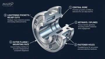
Five geometric features define how a shaft hub performs—and each carries dimensional requirements tied directly to function:
- Central bore — fits onto the mating shaft, held to ±0.0002 in to control fit type (clearance, transition, or interference); bore finish governs load transfer and assembly repeatability
- Keyways or splines — machined slots or teeth that transfer torque mechanically; width, depth, and angular position must be tightly controlled to prevent stress concentrations and fretting wear
- Fastener holes — threaded or through-holes for set screws, bolts, or retaining hardware that secure the hub axially on the shaft
- Outer flange or mounting face — the external interface where torque passes to gears, pulleys, or driven assemblies; flatness and bolt hole position tolerances directly affect mating part alignment
- Lightening pockets and relief cuts — undercuts, chamfers, and internal pockets that reduce mass without compromising structural integrity, a feature standard hubs rarely require
Together, these features explain why aerospace shaft hubs are far more complex to machine than their general-purpose counterparts.
How Shaft Hubs Differ from General Industrial Hubs
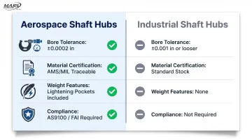
Aerospace shaft hubs operate under far more stringent requirements than their industrial counterparts:
- Tighter tolerances: Bore diameters held to ±0.0002 in vs. ±0.001 in or looser in industrial applications
- Certified materials: Full traceability to AMS or MIL specifications with mill test certificates and heat lot documentation
- Weight optimization: Thin-wall sections, lightening pockets, and material removal features not found in standard hubs
- Regulatory compliance: AS9100 quality systems, First Article Inspection (FAI), and dimensional reports required for aerospace procurement
Precision Requirements and Tolerances for Aerospace Shaft Hubs
Aerospace shaft hubs demand tighter tolerances than virtually any other manufacturing sector. Bore diameters are commonly specified to ±0.0002 in to ±0.0005 in, with concentricity and runout requirements measured in tenths of thousandths. These precision levels exist because shaft hubs operate in rotating assemblies where dimensional variation directly translates to vibration, accelerated wear, and reduced component life.
Bore Fit and Concentricity
The bore tolerance controls the interference or clearance fit between hub and shaft, which determines how the hub is installed and how securely it remains fixed during operation.
Fit Types:
- Clearance fits: Allow the hub to slide freely onto the shaft for removable or adjustable assemblies
- Transition fits: Provide a snug fit requiring light press force, used where hubs must be periodically removed
- Interference fits: Require significant press force and create a permanent mechanical bond for hubs that remain installed for component life
Concentricity and total indicated runout (TIR) requirements for aerospace shaft hubs are typically held to 0.0005 in or less. Any eccentricity in a rotating hub creates dynamic imbalance that accelerates bearing wear, seal degradation, and can introduce resonant vibrations at specific rotational speeds. How tight tolerances reduce premature failure is well-documented in precision rotating assemblies.
Surface Finish Requirements
Bore surfaces for press-fit aerospace shaft hubs typically require surface finishes in the range of 8–32 microinch Ra (roughness average). Finer finishes reduce stress concentration points that could initiate fatigue cracks and improve the uniformity of load distribution across the fitted interface.
M.A.R.'s Engineering's centerless grinding achieves finishes as fine as 4 μin with tolerances to 0.0001 in on shaft hub OD surfaces — precision that satisfies bearing interface and seal surface requirements without secondary operations.
Keyway and Spline Tolerances
Keyway width and depth tolerances are critical to torque transmission reliability. Oversized keyways create excessive clearance that allows angular play between hub and shaft, leading to impact loading and fretting wear during torque reversals. Undersized keyways cause assembly interference and stress concentrations at keyway corners. CNC milling and Wire EDM control these features far more consistently than manual broaching, delivering repeatable keyway dimensions across production runs without tool wear variation.
Where keyways handle moderate torque, spline features take over in higher-load applications — and they require even tighter control of pitch diameter, tooth profile, and lead accuracy. Errors in spline geometry cause uneven load distribution across teeth, concentrating stress in individual teeth and accelerating fatigue failure.
Thermal and Fatigue Considerations
Aerospace shaft hubs endure repeated loading cycles — takeoff, cruise, landing, engine restart — combined with temperature swings that drive material fatigue over a component's service life. Dimensional precision directly affects fatigue resistance: stress concentrations from rough bore surfaces, sharp corners, or keyway burrs all accelerate crack initiation.
Surface finish requirements and corner radii specifications are engineering-critical details that govern fatigue life, not cosmetic preferences. Machining processes must avoid:
- Work hardening from excessive cutting heat or tool pressure
- Residual tensile stress introduced by aggressive feeds or dull tooling
- Surface defects such as chatter marks, tool chipping scars, or built-up edge deposits
Each of these factors can reduce the fatigue life an aerospace engineer designed the component to achieve.
Best Materials for CNC Machined Aerospace Shaft Hubs
Material selection for aerospace shaft hubs involves balancing strength, weight, machinability, fatigue resistance, and corrosion performance. No single alloy suits every application—engineers select based on the hub's service environment, loading conditions, and operating temperature range.
Aluminum Alloys (6061, 7075)
Aluminum alloys are the most common choice for shaft hubs in moderate-temperature aerospace applications where weight reduction is a priority.
| Grade | Strength | Best For | Machining Note |
|---|---|---|---|
| 6061-T6 | Moderate | Actuator assemblies, flight control linkages, auxiliary drives (≤150°C) | Excellent machinability; cost-effective for medium-volume runs |
| 7075-T6 | High (≈mild steel at ⅓ the density) | Airframe hubs, landing gear actuators, gearbox interfaces | Higher hardness accelerates tool wear; superior fatigue resistance |
Titanium Alloys (Ti-6Al-4V)
Ti-6Al-4V is selected for shaft hubs operating in high-stress or elevated-temperature environments. The alloy offers an exceptional strength-to-weight ratio (comparable to high-strength steels at 40% lower weight), high fatigue resistance, and thermal stability up to approximately 315°C. Common applications include engine accessory drive hubs, compressor shaft interfaces, and landing gear components where both weight savings and structural performance are essential.
Machining Ti-6Al-4V demands controlled cutting speeds, consistent coolant application, and premium carbide or coated tooling. Its low thermal conductivity and tendency to work harden mean that cutting shortcuts lead to surface hardening—directly compromising fatigue life and dimensional accuracy.
Stainless Steel (17-4 PH, 15-5 PH)
Precipitation-hardening stainless steels combine high hardness after heat treatment with excellent corrosion resistance, making them ideal for aerospace shaft hubs in corrosive or high-wear environments.
17-4 PH reaches up to Rc 44 after aging, with corrosion resistance that outperforms conventional stainless grades. It suits hydraulic system hubs, actuator drive components, and applications where salt spray or hydraulic fluid exposure would corrode aluminum or carbon steel. Machining in the solution-annealed condition before final aging preserves dimensional accuracy.
15-5 PH offers similar hardness with improved toughness in the transverse direction—useful for hubs subjected to combined bending and torsional loads. Both grades follow the same machining-then-age-harden sequence.
Material Traceability Requirements
Regardless of alloy selected, aerospace procurement requires full material traceability. Mill test certificates documenting chemical composition, heat lot numbers, and conformance to AMS (Aerospace Material Specification) or MIL standards must accompany every material batch. M.A.R.'s Engineering's ISO-compliant quality systems maintain documentation from raw material receipt through final inspection. Material pedigree is tracked at every stage and available for customer audit or regulatory review.
CNC Machining Processes for Aerospace Shaft Hubs
Machining an aerospace shaft hub requires multiple complementary CNC operations performed in a specific sequence. No single process produces the complete part: proper sequencing of roughing, heat treatment (if required), semi-finishing, and finishing operations determines final dimensional quality while controlling residual stress and material distortion.
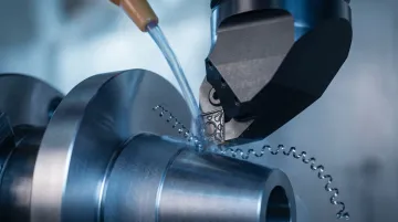
CNC Turning and Boring
CNC turning is the primary process for shaft hubs given their rotational symmetry. CNC lathes produce the outer diameter, internal bore, undercuts, chamfers, and cylindrical profiles with excellent concentricity because the part and cutting tool share a common axis of rotation.
Single-point boring operations following rough turning then refine the bore to final diameter, achieving the tight tolerances (±0.0002 in) and surface finishes required for precise shaft-to-hub fits.
CNC Milling for Keyways, Flanges, and Secondary Features
CNC milling operations machine keyways, bolt hole patterns, flange faces, and any non-cylindrical features after the hub's primary cylindrical geometry is established by turning. 4-axis CNC milling—available at M.A.R.'s Engineering—allows precise angular indexing for multi-position keyways, cross-holes, and mounting features without multiple manual setups that could introduce alignment error. Part indexers enable 360-degree rotational positioning, allowing the machine to access different angular positions while maintaining critical geometric relationships between features.
Wire EDM for Precision Keyways and Complex Internal Features
Wire EDM is well-suited for producing keyways and internal spline features in hardened shaft hubs, or in materials like titanium where conventional broaching introduces excessive tool wear and residual stress. Cutting by electrical discharge rather than mechanical force eliminates the cutting forces that could distort thin-wall hub sections or induce work hardening. M.A.R.'s Engineering maintains in-house Wire EDM capability, eliminating the lead times and coordination costs associated with outsourcing these operations.
Centerless Grinding for OD Finishing
Centerless grinding achieves the precise OD diameter and surface finish required where the hub interfaces with a bearing bore, housing, or seal. The grinding wheel removes material uniformly around the full circumference without deflection from cutting forces, delivering roundness and surface finish consistency that lathe finishing alone cannot match.
For hubs used in rotating assemblies, this precision is non-negotiable — dimensional variation at the OD directly causes vibration and shortens bearing life.
Process Sequencing and Fixturing Considerations
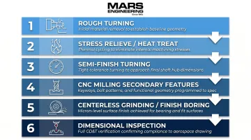
Getting the sequence right prevents costly rework after heat treatment and preserves geometric relationships across operations. A typical process flow follows this order:
- Rough turning to establish near-net geometry
- Stress relieve or heat treat (if material specification requires)
- Semi-finish turning to refine geometry after stress relief distortion
- CNC milling of secondary features (keyways, holes, flats)
- Centerless grinding or finish boring for final dimensional and surface quality
- Inspection at each critical stage
Precision fixturing—collets, mandrels, or soft jaws—is essential to maintain concentricity and prevent distortion of thin-wall hub sections during machining. Support parts consistently across operations to preserve the geometric relationships set in earlier steps.
Quality Standards and Compliance for Aerospace Shaft Hubs
Aerospace shaft hub procurement requires suppliers to demonstrate controlled quality systems with documented procedures, calibrated measurement equipment, and traceability throughout manufacturing. Two standards define the baseline expectations for most aerospace and defense programs:
- ISO Quality Management: Extends baseline quality controls with requirements for risk management, configuration control, and product safety — covering documented procedures for production control, inspection, and corrective action. M.A.R.'s Engineering maintains ISO-compliant quality systems with full traceability.
- Mil-1-45208A Compliance: A military inspection system standard covering inspection planning, first article inspection, in-process verification, and final inspection. M.A.R.'s Engineering's compliance ensures inspection records meet defense procurement requirements.
Dimensional Inspection and Documentation
Inspection methods used to verify shaft hub conformance include:
- Coordinate Measuring Machine (CMM): Measures bore diameter, concentricity, perpendicularity, and positional tolerances of bolt holes and keyways
- Surface Profilometers: Verify Ra (roughness average) measurements on bores and sealing surfaces
- Runout Gauging: Measures total indicated runout (TIR) to confirm concentricity of rotating surfaces
Full dimensional reports documenting actual measured values—not just pass/fail records—must accompany aerospace parts for traceability and long-term part history. These records support statistical process control and enable root cause analysis if field issues arise — making them a direct input into the First Article Inspection process.
First Article Inspection and Process Control
First Article Inspection (FAI) is required before any new shaft hub design enters production. Sample parts are fully inspected against drawing requirements, and all dimensions are documented. Only after FAI approval can full production begin.
Statistical Process Control (SPC) is used during production runs to detect dimensional drift before out-of-tolerance parts are produced. By monitoring key dimensions (bore diameter, concentricity, keyway width) across production batches, manufacturers can identify tool wear or process variation trends and make adjustments before rejects occur.
How to Choose the Right CNC Machine Shop for Aerospace Shaft Hubs
Selecting a precision machine shop for aerospace shaft hubs requires evaluating several critical factors. The criteria below separate shops capable of meeting aerospace requirements from those likely to create downstream quality and schedule problems.
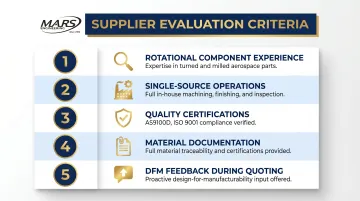
Evaluate each candidate against these five criteria:
- Rotational component experience: Documented history machining shafts, couplings, and bushings to tight tolerances. Multi-vendor supply chains increase tolerance stack-up risks—one defense case study found splitting hub and mating assembly production across suppliers produced out-of-specification parts once internal trial-fitting was no longer possible.
- Single-source operations: In-house turning, milling, grinding, and EDM under one roof reduces lead time and eliminates inter-supplier variation. Aerospace on-time delivery averages only 70%—one in three orders delivered late—largely because of multi-vendor coordination failures.
- Quality certifications: AS9100D certification (or ISO 9001 minimum for less demanding programs), documented First Article Inspection procedures, calibrated measurement equipment, and material traceability systems that meet AS9100D operational risk management requirements.
- Material documentation: Mill test certificates, heat lot records, and conformance documentation to AMS/MIL specifications. Full traceability from raw material receipt to final inspection is non-negotiable for aerospace work.
- DFM feedback during quoting: Shops that proactively flag tolerance conflicts, suggest corner radius changes to improve tool access, or propose material substitutions to cut cost without sacrificing performance prevent expensive redesigns after tooling investment.
M.A.R.'s Engineering checks each of these boxes. Founded in 1964 and operating from a vertically integrated facility in San Leandro, CA, the shop runs CNC turning, 4-axis milling, Wire EDM, and centerless grinding in-house alongside ISO 9001:2015/AS9100D certification and Mil-1-45208A inspection systems. All operations — from raw material receipt through final dimensional inspection — remain under one roof, eliminating the tolerance accumulation and scheduling gaps that multi-vendor chains introduce.
Before committing to production volume, request sample parts or a first article run. Pay attention to how quickly and thoroughly the shop responds to technical questions during quoting — that responsiveness is a reliable indicator of whether they have the process depth and quality culture to support a multi-year aerospace program.
Frequently Asked Questions
What is an aerospace shaft hub and what does it do?
An aerospace shaft hub is a precision rotational component that mounts onto a shaft to transmit torque to surrounding assemblies. It's used in engine drives, actuators, landing gear mechanisms, and gearboxes throughout aircraft systems to create reliable mechanical connections under cyclic loading.
What tolerances are typically required for CNC machined aerospace shaft hubs?
Bore diameter tolerances commonly reach ±0.0002 in to ±0.0005 in, with concentricity and runout requirements of 0.0005 in or less. Surface finishes range from 8–32 microinch Ra depending on fit type—significantly tighter than standard industrial specifications.
Which materials are most commonly used for aerospace shaft hubs?
The most common choices are aluminum alloys (6061 for moderate loads, 7075 for higher strength), titanium (Ti-6Al-4V for high-stress or elevated-temperature applications), and stainless steel (17-4 PH for corrosive environments). Selection depends on load, operating temperature, weight budget, and environment.
What CNC processes are used to machine aerospace shaft hubs?
Four core processes are typically involved:
- CNC turning and boring — establishes the cylindrical profile and bore
- CNC milling — adds keyways and secondary features
- Wire EDM — produces precision keyways in hardened materials
- Centerless grinding — achieves final OD dimensions and superior surface finish
What certifications should a CNC shop have to machine aerospace shaft hubs?
AS9100 certification (or ISO 9001 at minimum) and Mil-1-45208A inspection compliance are the baseline. Shops must also maintain full material traceability with mill test certificates, documented First Article Inspection procedures, and calibrated measurement equipment.
How is an aerospace shaft hub different from a standard industrial hub?
The differences go beyond just tighter tolerances (±0.0002 in vs. ±0.001 in or looser in industrial applications). Aerospace hubs require certified alloys with traceable documentation, weight-reduction features like lightening pockets, and AS9100 quality compliance — standards that general industrial work doesn't demand.