This guide covers how CNC lathe precision shaft machining works, which turning operations define precision, how to select materials and specify tolerances, what challenges arise and how skilled shops solve them, and what to look for in a machining partner.
TLDR:
- CNC lathes produce shafts with controlled concentricity, roundness, straightness, and surface finish; standard turning holds ±0.0005 in while centerless grinding reaches ±0.0001 in
- Core operations — rough/finish turning, threading, grooving, and boring — complete in minimal setups to preserve alignment
- Material choice (alloy steel, stainless, aluminum, titanium) directly impacts cutting parameters, achievable finish, and service life
- Chatter, thermal growth, and concentricity errors have proven CNC solutions when the right capabilities are in place
What Is CNC Lathe Precision Shaft Machining?
CNC lathe shaft machining is a computer-controlled turning process where cylindrical stock rotates in a chuck or between centers while a programmed cutting tool moves along the X (radial) and Z (axial) axes to produce shafts with specified diameters, geometries, and surface conditions. Unlike conventional manual turning, CNC eliminates operator variability by storing every cut parameter as a reusable program.
The CNC system controls spindle speed (RPM), feed rate (in/rev), depth of cut, and tool path sequences. Modern CNC turning centers provide precise positional control, with indexing increments as fine as 0.001° on rotary axes. This level of control ensures identical output from the first prototype to a high-volume production run.
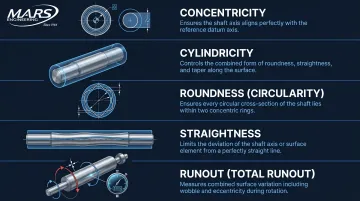
What separates "precision" shaft machining from standard turning is the focus on geometric tolerances beyond diameter alone:
- Concentricity: alignment of the rotational axis along the full shaft length
- Cylindricity: uniformity of the cylindrical form across its full surface
- Roundness: deviation from a true circle in cross-section
- Straightness: absence of bend or bow along the shaft axis
- Runout: total wobble measured at speed under real operating conditions
These tolerances determine whether the shaft performs without vibration, imbalance, or premature bearing wear. SKF bearing maintenance guidance confirms that dimensional control at this level is critical for bearing life and assembly fit.
Core CNC Turning Operations for Precision Shafts
Rough and Finish Turning
Precision shafts require a two-stage approach:
- Rough turning removes bulk material quickly at higher feed rates and depths, leaving controlled stock
- Finish turning takes light cuts at precise parameters to achieve final diameter and surface finish
This separation is essential for dimensional stability. Rough cuts introduce heat and stress that cause temporary expansion and micro-distortion. Allowing the workpiece to stabilize before the finish pass prevents dimensional drift. Tooling manufacturer Sandvik recommends using robust roughing inserts with 1.2 mm nose radius, then switching to finishing inserts with sharper geometry.
Example finish-turning parameters from Okuma for precision work: cutting depth 0.05 mm, feed 0.05 mm/rev.
Facing, Taper Turning, and Shoulder Creation
CNC handles three geometry-defining operations that manual methods struggle to complete in a single setup:
- Facing removes material from the shaft end to create a flat, perpendicular surface — critical for bearing seating and axial load distribution. An out-of-square face causes uneven preload and accelerated wear.
- Taper turning produces angled profiles for press-fit connections, tool holders, and tapered roller bearing seats. The CNC coordinates X and Z motion simultaneously to hold angle accuracy within arc-minutes.
- Shoulder turning creates distinct diameter steps for mounting gears, pulleys, or bearings. Completing all three in one setup preserves concentricity between features, which re-chucking on a manual machine cannot guarantee.
Threading, Grooving, and Keyway Operations
- CNC threading cuts external threads (for bolt/rod interfaces) or internal threads (for housings) through synchronized spindle-to-feed cycles. ASME B4.1 fit systems and machine indexing capabilities together enable controlled thread fits.
- Grooving creates seats for O-rings, snap rings, and seals. Even a slight miscut — 0.002 in too shallow or too wide — can cause pressure failure or seal extrusion. CNC holds groove width and depth to ±0.0005 in on production runs.
- Keyway slots transmit torque between shaft and gear or pulley, with positional accuracy relative to other features that depends entirely on staying in the same chucking throughout.
Drilling, Boring, and Center Support
Interior features follow a deliberate sequence — each step setting up the next for accuracy.
Center drilling at shaft ends enables tailstock support, essential for maintaining concentricity on long or slender shafts. The center hole provides a precise reference point for between-centers turning.
Drilling creates preliminary bores for oil channels, cooling passages, or bearing interfaces. Drills can wander, introducing runout that the next operation corrects.
Boring brings the bore to final diameter and roundness, correcting any runout from drilling. This achieves the precise H6 or H7 fits required for press-fitting bearings. NSK bearing catalogs specify typical housing fits of H8 and shaft fits around js6 for certain applications.
Centerless Grinding as a Precision Finishing Step
After CNC turning establishes shaft geometry, centerless grinding achieves tolerances of ±0.0001 in and surface finishes ≤16 RMS — levels beyond what turning alone can produce. The workpiece is supported between a grinding wheel and regulating wheel with no chucking, eliminating runout introduced by jaw contact.
Centerless grinding is the preferred final operation for bearing-surface diameters, seal journals, and any zone requiring the tightest tolerances. At M.A.R.'s Engineering, our centerless grinding capability delivers finishes to 4 μin Ra and holds tolerances to 0.0001 in — making it a core part of how we serve aerospace, medical, and industrial customers with the most demanding specifications.
Materials for Precision Shaft Machining
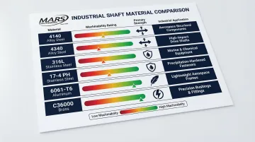
Material selection drives both shaft performance and machinability parameters — and each category comes with distinct trade-offs:
| Material | Machinability (% of AISI 1212) | Primary Advantages | Typical Applications |
|---|---|---|---|
| 4140 Alloy Steel | ~20–25% | High strength, fatigue resistance, heat-treatable | Power transmission shafts, automotive axles |
| 4340 Alloy Steel | ~50% | Superior toughness, deep hardening | Aerospace landing gear, heavy-duty driveshafts |
| 316L Stainless | ~45% | Corrosion resistance, biocompatibility | Medical implants, food processing equipment |
| 17-4 PH Stainless | ~48% | High strength after precipitation hardening | Valve stems, pump shafts |
| 6061-T6 Aluminum | ~270% | Low weight, excellent machinability | Aerospace actuators, electronics cooling |
| C36000 Brass | 100 (baseline) | Fastest machining, good conductivity | Fluid connectors, electrical terminals |
Machinability Impact on CNC Parameters:
Harder materials — stainless steel and titanium chief among them — require slower cutting speeds, rigid setups, and coated carbide or ceramic tooling to prevent built-up edge and maintain surface finish. At the other end of the spectrum, C36000 brass runs at 400–600 SFM and 6061-T6 aluminum at 300–800 SFM.
Titanium is more complicated. Industry sources conflict on optimal speeds — some cite 60–120 m/min, others allow 230–300 m/min under specific conditions. A 2023 study found optimal dry turning at 66.97 m/min with tightly controlled feed and depth parameters.
Specialty Materials
Two materials deserve extra attention for precision shaft work:
- Titanium (Ti-6Al-4V): Standard in aerospace and implant-grade applications. Careful speed management and consistent coolant flow are non-negotiable — work hardening sets in quickly, degrading surface finish and accelerating tool wear.
- PEEK (polyetheretherketone): A high-performance polymer gaining ground in medical and semiconductor shafts. Victrex recommends 100–300 m/min at 0.1–0.7 mm/rev feeds; Drake Plastics targets 300–800 ft/min at 0.025 in depth. Both flag rapid heat buildup as the primary risk — sharp tooling and proper fixturing are non-negotiable to prevent part distortion.
Achieving Tight Tolerances, Surface Finish, and Quality Control
Tolerance Hierarchy for Precision Shafts
ISO 286 defines IT tolerance grades as the normative basis for linear size tolerances. These grades scale with nominal diameter, creating a predictable framework for specifying fits.
Example: SKF recommends at least IT6 for normal bearing shafts. For a 150 mm shaft, cylindricity tolerance is IT5/2 = 9 µm (radius), equivalent to 18 µm on diameter.
Process capability by operation:
- Standard CNC turning: ±0.0005 in typical for production shafts
- Precision CNC turning: tighter control with in-process monitoring and tool compensation
- Centerless grinding: ±0.0001 in for bearing journals and seal surfaces
Geometric Tolerances That Matter
Beyond diameter, shaft-specific geometric controls include:
- Concentricity — how aligned the axis is across the full length; measured by rotating the shaft in V-blocks and tracking indicator deviation
- Roundness/Circularity — deviation from a true circle in cross-section; caused by chatter, deflection, or worn spindle bearings
- Cylindricity — combination of roundness and straightness; the envelope within which the entire surface must lie
- Total runout — combined effect at speed; measured by rotating the shaft and sweeping an indicator along its length
Controlling these requires between-centers turning, steady rests, and dialed-in cutting parameters — not just inspection after the fact.
Surface Finish Specifications
Bearing seats typically require Ra values of 0.4–0.8 µm (16–32 µin). Seal journals may require even finer finishes to prevent leakage. General shaft surfaces are less critical.
How operations deliver finish:
- Finish turning: 0.8–1.6 µm Ra typical with sharp inserts and proper speeds
- Centerless grinding: ≤0.4 µm Ra (16 RMS or better) for critical zones
Surface finish has real functional consequences. A rough seal journal accelerates O-ring wear by 3× to 5× compared to a properly finished surface — and that's before factoring in bearing film formation and friction losses.
Quality Control Methods
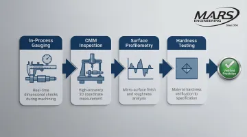
Precision shafts require verification at multiple stages, not just final inspection:
- In-process gauging — measures diameter at the machine before the final cut; operators adjust tool offsets in real time to compensate for wear and thermal drift
- CMM inspection — verifies geometric tolerances post-machining; modern CNC lathes integrate measurement systems for automated verification
- Surface profilometry — tactile or optical systems trace the surface profile and compute Ra values on critical zones
- Hardness testing — confirms material properties after heat treatment, ensuring the shaft meets strength and wear resistance specs
M.A.R.'s Engineering maintains ISO-compliant quality systems with full traceability — a requirement for the aerospace, medical, and defense sectors the shop regularly serves.
Steady Rests and Follower Rests
On long shafts, cutting forces cause the workpiece to deflect away from the tool, producing taper and out-of-roundness. Steady rests provide fixed support at a set point along the shaft length. Follower rests travel with the tool carriage, maintaining support directly at the cutting zone. Both are essential for shafts with high length-to-diameter ratios (L/D > 10:1).
Common Shaft Machining Challenges and Solutions
Chatter and Vibration
Chatter produces surface waviness, degrades finish, and accelerates tool wear. The root causes are typically insufficient workpiece rigidity, excessive tool overhang, or cutting parameters that excite resonant frequencies.
To address this:
- Use between-centers or steady rest support for long shafts
- Reduce tool overhang to minimum practical length
- Adjust spindle speed to move away from chatter-prone RPM ranges
- Select cutting inserts with chip-breaker geometry suited to the material
Sandvik's tooling guidance emphasizes separate roughing and finishing strategies to manage vibration and improve geometry.
Thermal Growth and Dimensional Drift
Cutting heat causes the workpiece to expand during machining, so dimensions measured at temperature differ from those at room temperature. Parts that check good on the machine can come back out of tolerance after cooling.
Controlling for this requires:
- Apply flood coolant to stabilize temperature
- Take finish cuts slowly to minimize heat input
- Allow parts to thermally normalize before final measurement
- Specify temperature-controlled measurement environments for critical tolerance verification
Okuma documents thermal stability of 0.3 µm over 3,000 minutes on sub-spindles and 0.2 µm over 1,800 minutes on standard spindles — figures that show how much thermal management is built into modern machine design.
Thermal drift and tool wear often compound each other: a machine running hot while the insert degrades will produce diameter drift that's difficult to attribute to either cause alone.
Tool Wear and Diameter Drift
A worn cutting insert shifts the effective cutting diameter over time, causing shafts to taper along their length. On long production runs, the first part and the last can differ by 0.002 in or more.
Managing this drift comes down to proactive monitoring:
- Program tool wear compensation with automatic offset updates
- Set tool life limits with mandatory insert changes before critical wear
- Use coated carbide grades rated for the shaft material being cut
- Monitor in-process with gauging to detect drift early
Tooling manufacturers publish insert dimensional tolerances (for example, ±0.08 mm for certain sizes), which feed directly into offset compensation strategies.
Concentricity Errors from Re-Chucking
Every time a shaft is removed and re-installed, there's risk of introducing runout relative to the original turning axis. Even precision chucks carry jaw alignment tolerances of 0.0005–0.001 in — enough to push a tight-tolerance diameter out of spec.
The most reliable fixes minimize handling altogether:
- Complete as many features as possible in a single setup
- Use between-centers turning for critical diameter passes
- Verify runout with a dial indicator after each setup before cutting begins
- Consider sub-spindle transfer on multi-axis CNC lathes to eliminate manual handling
How to Choose a CNC Shaft Machining Partner
Evaluate Tolerance and Surface Finish Capability
Ask specifically whether the shop can hold the diameter tolerances and Ra values your application requires. Confirm they have both CNC turning and post-turning grinding in-house. Outsourcing the grinding step to a sub-supplier adds lead time, cost, and alignment risk between operations.
Verify Quality Systems and Certifications
ISO 9001 compliance ensures documented process controls and traceability from raw material to finished part. For defense, aerospace, or medical shafts, confirm whether the shop meets AS9100 D or relevant regulatory standards.
Standard deliverables to require from any qualified shop:
- First-article inspection reports with dimensional data
- In-process measurement records tied to lot traceability
- Material certifications matching the specified alloy and heat
Prioritize Single-Source Manufacturing Capability
A shop that handles turning, grinding, finishing, plating, and assembly under one roof eliminates coordination overhead, lead time gaps, and quality hand-off risks of using multiple vendors.
M.A.R.'s Engineering has operated as a single-source precision manufacturer since 1964, serving aerospace, medical, automotive, and industrial customers from their San Leandro, CA facility. Their integrated capabilities include:
- CNC turning to ±0.0005 in tolerance
- Centerless grinding to 4 μin Ra and tolerances to 0.0001 in
- In-house finishing: hard chrome, nickel plating, and black oxide
- ISO-compliant quality systems with full material traceability
Frequently Asked Questions
What is CNC precision machining?
CNC precision machining is a computer-controlled manufacturing process that uses programmed instructions to remove material from a workpiece and achieve tight dimensional tolerances and consistent geometry. It eliminates manual variability, ensuring repeatability across production runs.
Which type of lathe is best suited for precision machining in industries?
Slant-bed CNC lathes offer superior rigidity and chip evacuation for high-precision shaft work. Horizontal CNC lathes with live tooling are widely used for general industrial shaft production. The best choice depends on part diameter, length, material, and required tolerance level.
Can you CNC machine PEEK?
Yes. PEEK is used for medical and semiconductor shaft applications and machines well when parameters are controlled. It requires sharp tooling and managed cutting speeds, as the material is prone to thermal distortion if heat is not kept in check.
What tolerances can CNC lathe shaft machining achieve?
Standard CNC turning typically holds ±0.0005 in. Precision turning with in-process monitoring can reach tighter levels. Centerless grinding achieves tolerances as tight as ±0.0001 in. The application's fit type (running, sliding, press) determines which level is necessary.
What is the difference between CNC turning and centerless grinding for shafts?
CNC turning creates shaft geometry: diameters, threads, grooves, and shoulders. Centerless grinding is a finishing operation that achieves the tightest diameter tolerances and finest surface finishes that turning alone cannot reach.
How do I ensure concentricity across a long precision shaft?
Use between-centers turning to maintain a consistent rotational reference, and apply steady rests or follower rests for mid-span support on slender shafts. Minimize setups and verify concentricity with dial indicators after each chucking before committing to finish cuts.