Introduction
A single out-of-tolerance shaft can throw off every joint downstream. That's the reality robotics engineers face, and it's why component precision isn't a preference — it's a structural requirement.
Custom CNC machining uses computer-controlled machine tools to cut, mill, turn, and grind raw materials into precise robot component geometries. It's the dominant manufacturing method for robotic systems because almost nothing else reliably delivers the tolerances, strength-to-weight ratios, and repeatability these applications demand — from early prototypes through full production runs.
Research from kinematic calibration studies shows that absolute positioning accuracy of open-chain industrial robots is typically limited to ±1 to 2 mm due to kinematic error stacking. Dimensional deviations in individual components compound through the kinematic chain.
That amplification effect makes precision machining non-negotiable: a 0.05 mm error at a single joint can translate into millimeters of positioning error at the end effector. This guide covers how to apply CNC machining to robot components — from material selection and tolerance planning to process choices and production scaling.
TL;DR
- Custom CNC machining uses computer-programmed instructions to remove material and produce precise robotic parts, including joints, gears, end effectors, and structural frames
- Tolerances as tight as ±0.0002 in. (5 µm) are achievable, with support for complex geometries across metals and engineering plastics
- Production moves from CAD/CAM programming through material setup, multi-axis machining, and finishing to final quality inspection
- Part quality depends on material choice, complexity, tolerance requirements, and a shop's in-house capabilities — finishing, fixturing, and quality systems included
- For high-volume, low-complexity parts, injection molding or die casting often outperforms CNC on cost and speed
What Is Custom CNC Machining for Robot Components?
Custom CNC machining uses computer numerical control machines that follow programmed toolpaths to remove material from metal or plastic stock, producing parts to precise dimensional specifications without manual intervention. The process is governed by standardized programming languages — primarily ISO 6983 (G-code). G-code specifies data formats for positioning, line motion, and contouring control systems.
The outcome is dimensionally exact, repeatable components that meet the tight mechanical requirements of robotic joints, actuators, structural frames, and end effectors. Unlike standard commodity CNC production, custom CNC machining for robotics typically involves one-off or low-volume runs of application-specific geometries. That distinction drives several added requirements:
- Multi-axis setups to reach complex contours in a single fixturing
- Specialized tooling matched to the material and geometry of each part
- Stricter tolerance stacks — tighter cumulative variation limits across mated components than general-purpose machining demands
Why CNC Machining Is Essential for Robotic Parts
Precision and Dimensional Accuracy
Robotic systems amplify small errors through their kinematic chain — a dimensional deviation at one joint compounds through each subsequent axis. Advanced 5-axis machining centers can achieve positioning accuracies down to 3 µm and volumetric accuracies of less than 13 µm throughout the work area. In specialized micro-milling applications, tolerances as tight as ±0.0002 inches (2–3 µm) and surface finishes as fine as Ra 0.05 µm are achievable, eliminating the need for secondary polishing.
These precision levels are required for bearing fits, gear meshes, and sensor seats where even micron-level deviations introduce backlash, hysteresis, and positioning errors that degrade robot performance.
Speed of Iteration
CNC machining translates directly from a CAD file to a physical part, meaning engineering teams can prototype, test, and revise robot component designs in days rather than weeks. Development programs routinely run multiple design cycles before production release, and days-per-iteration matters.
CNC Machining vs. Casting Lead Times:
| Production Phase | CNC Machining | Casting |
|---|---|---|
| Tooling/Setup | 1–3 days | 4–12 weeks (mold build) |
| First Article | 3–7 days | 6–14 weeks |
| Production (per batch) | 1–3 weeks | 2–4 weeks |
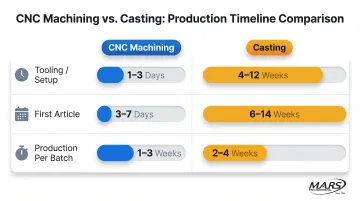
Via Rivcut: Casting vs. Machining Lead Time Comparison
The absence of mold fabrication time gives CNC machining a substantial advantage during the iterative design phase.
Complex Geometry Capability
Multi-axis CNC milling allows lightweighting pockets, internal passages, contoured joint housings, and intricate connection features to be machined in a single setup, reducing error from multiple part repositionings and enabling the compact, integrated designs modern robots require. Robotic joint housings are a clear example: internal volumes must accommodate bearings, sensors, and cable routing while maintaining structural rigidity — all achievable in one machining sequence.
Material Versatility
Robots require a specific range of engineering materials, and CNC machining is one of the few processes compatible across all of them. This gives engineers full flexibility to match material to function within a single manufacturing workflow.
A robotic arm assembly, for instance, might combine:
- 7075 aluminum for the upper arm structure (high strength-to-weight ratio)
- Stainless steel for the joint reducer housing (wear and corrosion resistance)
- PEEK for electrical insulator bushings (dielectric properties, chemical resistance)
All three are manufacturable using the same CNC process family.
Repeatability Across Production Runs
Once a CNC program is validated on a prototype, it can be run consistently across any batch size , delivering identical parts whether the order is a 5-unit pilot or a 500-unit production run. For robot assembly lines, that dimensional consistency means components are truly interchangeable, eliminating hand-fitting and selective assembly — two of the most time-consuming steps in robotic system integration.
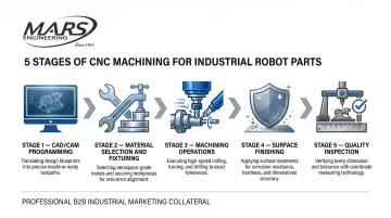
How Custom CNC Machining Works for Robot Parts
A robot component design moves from a 3D CAD model through CAM programming, machine setup, cutting operations, and surface finishing before passing quality inspection — each stage directly affects the dimensional and functional quality of the final part.
The process is controlled by the CNC program (toolpath, feed rate, depth of cut, spindle speed), the fixturing approach, and the shop's quality control checkpoints. A skilled machinist's role shifts to programming, setup verification, and in-process inspection rather than manual cutting.
Step 1: Design Review and CAM Programming
The machinist or process engineer reviews the CAD model for manufacturability — identifying features that may require design-for-manufacturing (DfM) adjustments, selecting the appropriate machine type (milling, turning, multi-axis), and generating the CAM toolpath that will drive the machine. Errors caught at this stage are far cheaper to fix than after material has been cut.
NIST research indicates that inadequate design and modeling data lead to $8.40 billion spent annually on engineers answering questions and clarifying documentation, with an additional $3.84 billion spent by machinists resolving the same issues.
The CAM software generates toolpaths based on selected machining operations, tools, and parameters. A post-processor then translates these toolpaths into machine-specific ISO 6983 G-code instructions that direct the CNC machine's movements.
Step 2: Material Selection, Fixturing, and Machine Setup
Engineers select stock material based on the component's load requirements, weight targets, and operating environment. The workpiece is then fixtured securely (critical for tight-tolerance robot parts), cutting tools are loaded, and the CNC program is verified with a dry run or simulation before cutting begins.
In-house custom tooling capability — such as Wire EDM for making specialized fixtures and cutting tools — significantly reduces setup lead time and cost for complex robot parts, enabling faster cycle times and lower total production costs.
Step 3: Machining Operations, Surface Finishing, and Inspection
The machine executes programmed operations (milling, turning, drilling, grinding) in sequence, removing material to achieve the specified geometry. Surface finishing steps follow machining to meet functional requirements like friction reduction, corrosion resistance, or wear hardness. Common finishes for robotic components include:
- Anodizing for aluminum corrosion resistance
- Hard chrome plating for wear resistance on bearing surfaces
- Passivation for stainless steel corrosion protection
- Polishing for smooth, low-friction surfaces
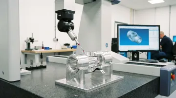
Final inspection — using coordinate measuring machines (CMM) or precision gauges — verifies that all critical dimensions and tolerances meet specification before the part ships. The ISO 10360 series establishes standardized procedures for CMM acceptance and reverification tests, ensuring consistent performance. When measured values fall close to specification limits, ISO 14253-1 defines decision rules for proving conformity, explicitly requiring that measurement uncertainty be taken into account to avoid costly disputes between manufacturers and buyers.
Key Robot Components Made with Custom CNC Machining
Structural Components and Joint Housings
Robot arms, shoulder and elbow joints, wrist housings, and mounting brackets are among the most common CNC machined parts. They require complex geometries, lightweighting features, and tight alignment surfaces — typically machined from aluminum alloy (6061 or 7075) or titanium for high-performance or mobile robotic platforms.
7075-T6 aluminum is specifically noted for use in robotic hands and housings due to its high strength-to-weight ratio and ability to be hard-anodized.
Gears, Shafts, and Transmission Components
Robotic joint reducers (harmonic drives, planetary gearboxes) and the shafts and drive components connected to them require ultra-tight tolerances on tooth pitch, concentricity, and coaxiality. CNC turning and gear hobbing are the standard processes for these parts, and even small deviations degrade robot positioning accuracy and introduce backlash.
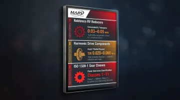
Tolerance Requirements for Precision Reducers:
- Nabtesco RV reducers require concentricity tolerances of 0.03–0.05 mm depending on frame size
- Harmonic Drive components require axial and radial runout tolerances (TIR) ranging from 0.020–0.060 mm for output flanges and shafts
- Robotic joint gears are governed by ISO 1328-1, which defines flank tolerance classes (1 to 11) for cumulative pitch, single pitch, and profile deviations
End Effectors and Grippers
End-of-arm tooling (EOAT) — the grippers, suction cups, tool changers, and specialized fingers that interact with the robot's work environment — are custom-designed and CNC machined. They must meet precise dimensional requirements for grasp force, part contact geometry, and attachment to the robot's wrist.
Representative EOAT Repeatability Requirements:
| Component Type | Manufacturer/Model | Repeatability |
|---|---|---|
| Tool Changer | ATI QC-46 | 0.015 mm (0.0006 in) |
| Parallel Gripper | Schunk PGN-plus | 0.02 mm |
| Miniature Gripper | Schunk EGP 64 | ±0.2 mm |
Industrial EOAT components consistently require repeatability in the 0.015–0.02 mm range to ensure precise part handling and tool swapping.
Sensor Mounts and Motor Enclosures
Sensor and motor housings are deceptively demanding. Dimensional errors don't cause obvious mechanical failures — they introduce noise into the robot's feedback loop and degrade control performance over time. Key requirements include:
- Vision, force-torque, and encoder mounts: tight flatness and coaxiality specs to ensure reliable sensor data
- Motor enclosures: precise bore fits for both the motor body and the output shaft bearing
- Alignment surfaces: must be machined consistently to prevent sensor drift across production units
Custom Jigs, Fixtures, and Assembly Trays
Robotic assembly and operation often require custom fixtures to hold workpieces precisely during assembly. These fixtures are natural CNC machining candidates — typically one-off or low-volume aluminum parts. Short lead times and consistent dimensional accuracy are critical: the robot depends on fixtures to locate parts repeatably, every cycle.
What to Know Before Choosing CNC Machining for Robot Parts
Factors That Affect Outcomes
Key variables that directly affect CNC machining results for robot parts include:
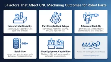
- Material machinability and hardness — affects tool life, cycle time, and achievable surface finish
- Part complexity and number of setups required — each setup introduces opportunity for positional error
- Tolerance stack across mating components — cumulative tolerances determine assembly fit
- Batch size — affects amortization of setup time and programming costs
- Shop's specific equipment capabilities — including axis count, maximum travel, available finishing processes, and in-house quality control systems such as CMM inspection
A shop with ISO-compliant quality systems and in-house finishing (plating, polishing, grinding) provides more consistent outcomes and shorter total lead times than one that subcontracts these steps. Shops with in-house Wire EDM capability can produce custom tooling with minimal lead time and low cost, reducing both setup time and per-part cycle time for complex components.
Common Misconceptions
Tighter tolerances are always better: Over-specifying tolerances unnecessarily drives up machining cost and time without improving robot function. Research indicates that reducing a functional variation requirement from 0.5 mm to 0.02 mm doubles manufacturing cost, and tightening it further to 0.01 mm triples the cost. Engineers should specify only the tolerances required by the actual fit and function of each feature.
CNC machining and CNC robotics are the same thing: CNC machining is a subtractive manufacturing process controlled by programmed toolpaths. CNC robotics refers to robotic arms used to automate tasks including machine tending, welding, or material handling. They are different technologies serving different functions.
Prototype-grade parts are the same as production-grade parts: Prototypes verify geometry and fit, but production parts require validated programs, tighter process controls, and documented inspection records to ensure consistency across batches and full traceability.
When CNC Machining May Not Be the Right Choice
CNC machining is not optimal in several scenarios:
Very high-volume, geometrically simple parts: Identical plastic housings in the tens of thousands are often better suited to injection molding due to lower per-part cost at scale. The production volume threshold where plastic injection molding becomes more cost-effective typically falls between 500 and 1,000 units, as the high initial mold fabrication costs ($1,500 to $100,000+) are amortized over the larger part count, dropping per-part costs substantially.
Parts with internal cavities or organic shapes that cannot be reached by a cutting tool: These may require additive manufacturing (metal 3D printing) or casting instead. CNC is a subtractive process limited by tool access.
Standard catalog items: Components like bearings and off-the-shelf fasteners should be sourced commercially rather than custom-machined, as custom machining adds cost without functional benefit.
Process selection should always be driven by engineering requirements, not habit. When injection molding, casting, or commercial sourcing can meet the functional need at lower cost, those are the right answers.
Frequently Asked Questions
How much does custom CNC machining cost?
Cost depends on material, part complexity, tolerance requirements, and batch size — a simple aluminum bracket may run tens of dollars per part at volume, while a multi-feature titanium housing can reach several hundred. Material machinability and cycle time are the largest drivers: exotic alloys wear tools faster and demand slower feed rates, pushing costs well above 6061 aluminum. Submit a fully detailed CAD file with tolerance callouts for an accurate quote.
Can AI do CNC machining?
AI is increasingly used in the CAM programming stage to generate and optimize toolpaths, and in quality control to automate inspection — but the physical cutting is still performed by CNC machine tools operated and overseen by skilled machinists. For example, Siemens NX CAM uses AI (Lambda Function) to suggest optimal tools, recommend cutting parameters, and generate toolpaths from shop floor feedback. AI assists the process — it does not replace the machine or the human judgment required for setup and verification.
What materials are best for CNC machined robot parts?
Material choice depends on load requirements, environmental conditions, and weight constraints. Common options include:
- Aluminum (6061, 7075) — lightweight structural parts and housings
- Stainless steel — gears and shafts needing strength and corrosion resistance
- Titanium — high-performance applications where weight savings justify the cost
- Engineering plastics (PEEK, Delrin) — low-friction or electrically insulating components
What tolerances can CNC machining achieve for robotic components?
Precision CNC machining can hold tolerances of ±0.0002 in. (±5 µm) or tighter on critical features, and surface finishes as fine as Ra 0.8 µm (or lower with post-processing) are achievable — both critical for the repeatable joint movements and precise sensor mounting that robot performance depends on. These capabilities require specialized equipment and rigorous process control.
Can CNC machining support both prototyping and production runs for robotic parts?
Yes. Prototype parts run from the same CAD files as production parts, so once the design is validated, the same programs and setups carry forward into volume runs with consistent dimensional quality. There's no need to re-validate manufacturing processes when moving from development to production.
What is the difference between CNC milling and CNC turning for robot parts?
Milling uses rotating cutting tools to create prismatic shapes, pockets, and complex contours — ideal for housings, brackets, and structural components. Turning rotates the workpiece against a stationary tool to produce cylindrical parts like shafts, pins, and gears. Many robot components require both, handled on a turn-mill center or across two setups.