Introduction
Guide bushing or no guide bushing — it's one setup decision, but it touches everything: part geometry, achievable tolerances, material costs, and bar remnant waste. Whether a Swiss-type machine runs in standard bushing mode or chucker (non-bushing) mode isn't a minor configuration detail. It's a choice rooted in the physics of workholding, the economics of bar stock, and the geometry of the part itself.
Pick the wrong mode and you'll see it in the results: deflection errors on slender parts, excessive bar remnant, inflated material costs, or slower throughput on short-part jobs. This guide breaks down how each mode works, where each excels, and the specific part and material conditions that should drive your decision.
TLDR
- Guide bushing mode stabilizes bar stock close to the cutting tool—best for long, slender parts with L/D ratios above 3:1 and tight tolerances
- Chucker mode pulls the guide bushing, converting the Swiss machine into a CNC-lathe-style setup suited for short, stout parts
- Bushing mode requires precision-ground bar stock and leaves longer remnants; chucker mode runs standard cold-drawn stock with less waste
- Many modern Swiss machines are convertible—they can operate in either mode, giving shops flexibility across job types
Bushing vs. Non-Bushing: Quick Comparison
The choice between guide bushing and chucker mode isn't just about capability—it's about economics. The table below breaks down how the two modes compare across the factors that affect part quality, material cost, and production efficiency:
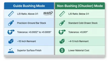
| Factor | Guide Bushing Mode | Non-Bushing (Chucker) Mode |
|---|---|---|
| Best Part Geometry | L/D ratio > 3:1, long slender parts | L/D ratio < 3:1, short stout parts |
| Bar Stock Type | Precision-ground (centerless ground) | Standard cold-drawn |
| Bar Stock Cost | Up to 4x higher | Baseline cost |
| Achievable Tolerance | ±0.0002" to ±0.0005" | ±0.001" (typical) |
| Surface Finish | Superior, no marring | Good for most applications |
| Bar Remnant Length | ~10 inches | ~4-5 inches |
| Changeover Time | 30-45 minutes (modern machines) | Same |
The 4x Material Cost Multiplier
Precision-ground bar stock required for guide bushing mode can cost up to four times more than standard cold-drawn stock. This premium buys diameter consistency within 0.002" of nominal—necessary to prevent the bar from jamming or rattling in the guide bushing. Standard cold-drawn stock, with its looser tolerances, works fine in chucker mode because the collet grip is more forgiving.
The Remnant Waste Factor
Guide bushing mode leaves approximately 10 inches of unusable bar remnant at the end of each bar, compared to just 4-5 inches in chucker mode. On expensive materials like titanium or stainless steel, that extra 5-6 inches of scrap per bar can translate to hundreds of dollars in wasted material across a production run of several thousand parts.
What is Guide Bushing Mode?
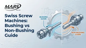
Guide bushing mode is the defining feature of Swiss-type machining. The guide bushing is a precision-fitted sleeve positioned just ahead of the cutting zone—typically 1 mm to 3 mm from the tool tip—that supports the bar stock radially throughout the machining operation. The headstock slides along the Z-axis, feeding the bar through the bushing as tools cut right beside it.
The Deflection Physics: Why the $L^3$ Law Matters
The advantage of guide bushing mode is rooted in basic mechanics. Deflection ($\delta$) of a cantilever beam under load follows the formula $\delta = PL^3/3EI$, where $L$ is the unsupported length. Because deflection increases as the cube of the distance from the support to the cutting force, even a small increase in unsupported length causes exponential deflection growth.
By positioning the guide bushing within millimeters of the cut, Swiss machines reduce the effective unsupported length ($L$) to nearly zero—virtually eliminating deflection even under aggressive tool pressure. This is what enables Swiss machines to produce long, slender parts to tight tolerances without vibration or bending.
Guide Bushing Types: Rotary vs. Fixed
There are two main guide bushing designs, each suited to specific applications:
| Bushing Type | Operational Mechanic | Best Applications | Drawbacks |
|---|---|---|---|
| Rotary | Rotates with the bar stock | Larger diameters, tolerances > ±0.0005", superior surface finish | Slightly lower absolute precision |
| Fixed | Remains stationary while bar spins | Ultra-tight tolerances, smallest diameters | Risk of marring the OD |
The bushing type determines more than just tolerance capability—it directly affects what bar stock you can run through it.
Bar Stock Requirements: Why Precision-Ground Stock Is Mandatory
Guide bushing mode demands bar stock with minimal diameter variation—typically within 0.002" of nominal. If bar stock varies beyond the guide bushing's allowable clearance, the bar can stick (if too large) or rattle (if too small), producing inconsistent sizing and surface finish.
Centerless-ground bar stock is the standard specification for this reason. Standard cold-drawn stock carries looser diameter tolerances that cause fitment problems in bushing mode—when sourcing material, always confirm ground stock is available for your diameter before committing to this process.
Use Cases of Guide Bushing Mode
Guide bushing mode comes into play when a part's length, required tolerance, or surface finish simply can't be held reliably with a free-hanging workpiece. The longer and thinner the part, the more cutting forces cause deflection—and deflection kills precision.
Part Profiles That Demand Guide Bushing Mode
High L/D ratio parts (length-to-diameter ratio exceeding 3:1, especially above 6:1) are the primary candidates:
- Long shafts and pins
- Bone screws and orthopedic implants
- Aerospace fasteners
- Connector pins and contact probes
- Hydraulic actuator pins
- Catheter components
When machined length exceeds the diameter by a wide margin, unsupported stock will deflect under cutting forces. The guide bushing eliminates that flex by supporting the bar stock within a fraction of an inch of the cut—keeping the tool and workpiece in a fixed, repeatable relationship throughout the operation.
Industries Where Guide Bushing Mode Dominates
Guide bushing mode is the production standard across several regulated and high-stakes industries:
- Medical devices: Surgical screws, spinal implants, catheter hinges, and bone pins require tolerances between ±0.0002" and ±0.0005" with exceptional concentricity. Guide bushing support is the only reliable way to hold those specs at volume.
- Aerospace: Titanium fasteners, fuel system fittings, and actuator pins demand tight tolerances over long lengths—exactly the combination where unsupported turning fails.
- Electronics: Connector pins, test probes, and contact extensions require surface finish consistency that guide bushing mode delivers run after run.
- Defense: Small-caliber components and precision ordnance parts call for both tight tolerances and full traceability, making guide bushing the default process.

The guide bushing itself is manufactured to coaxiality tolerances around 0.0002 inches. That level of alignment is what gives regulated industries the confidence to validate and certify parts produced this way.
What is Non-Bushing (Chucker) Mode?
Non-bushing mode (also called chucker mode) operates a Swiss-type machine with the guide bushing assembly removed. The bar is gripped only by the chucking collet in the headstock. Without the bushing, the machine behaves similarly to a conventional CNC lathe—the tool engages the workpiece without the near-cut support that defines Swiss turning.
Core Operational Benefits
- Accepts standard cold-drawn bar stock instead of precision-ground stock, cutting material costs on every run
- Reduces remnant length from ~10 inches down to ~4-5 inches, improving yield per bar and lowering scrap in high-volume production
- Allows mode switching in 30 to 45 minutes on modern convertible machines, making batch scheduling by mode practical
The Limitation: Deflection Risk
These material and yield advantages come with a trade-off. Without bushing support near the cut, any part with a high L/D ratio will experience tool-pressure-induced deflection, compromising dimensional accuracy. Parts with L/D ratios above 3:1 should not be run in chucker mode — out-of-tolerance results are likely.
Use Cases of Non-Bushing (Chucker) Mode
Chucker mode is the right choice when part geometry doesn't require guide bushing support—and when material cost or yield is a priority.
Part Profiles Suited to Chucker Mode
Chucker mode works best for short, compact turned parts where length doesn't significantly exceed diameter:
- Bushings and sleeves
- Short spacers and standoffs
- Threaded fittings and adapters
- Small flanged parts
- Knurled knobs or grips
- Components requiring heavier turning passes
The rigid collet-only grip can handle heavier cuts better than guide bushing mode for these stout geometries.
Operational Flexibility Advantage
Shops that run a mix of short and long parts on convertible Swiss machines can schedule chucker jobs in batches to minimize mode changeover frequency. Since changeovers take approximately 30 to 45 minutes on modern machines, batching similar-mode jobs cuts setup downtime and keeps machines running.
Bushing vs. Non-Bushing: Which Should You Choose?
The decision framework is straightforward: start with part geometry, layer in tolerance requirements, then evaluate total material cost.
Step 1: Evaluate L/D Ratio
If the part's machined length exceeds three times its diameter, guide bushing mode is typically required to prevent deflection and maintain tolerance. The 3:1 L/D threshold is an industry-wide rule based on the deflection physics discussed earlier.
If the part is short and compact relative to its diameter, chucker mode is a legitimate and often more cost-efficient choice.
Step 2: Layer in Tolerance and Surface Finish Requirements
For jobs requiring tight tolerances—especially concentricity and roundness—bushing mode provides approximately 50% improvement in roundness over starting material. For example, bar stock with 0.002" TIR (Total Indicator Reading) can be machined to 0.001" TIR in guide bushing mode.
That precision comes at a cost: guide bushing mode requires higher-grade bar stock. Evaluate whether the tolerance specification actually demands bushing mode, or whether chucker mode accuracy is sufficient.
Step 3: Calculate Total Material Cost
Mode selection affects per-part material cost, and those differences compound quickly at production volume.
Example:
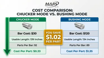
- 12-foot bar of 303 stainless, 0.5" diameter
- Cold-drawn: $30/bar
- Precision-ground: $120/bar (4x multiplier)
- Part length: 1.5 inches
Chucker mode:
- Usable length: 12 feet - 5 inches = 139 inches
- Parts per bar: 139 / 1.5 = 92 parts
- Material cost per part: $30 / 92 = $0.33
Bushing mode:
- Usable length: 12 feet - 10 inches = 134 inches
- Parts per bar: 134 / 1.5 = 89 parts
- Material cost per part: $120 / 89 = $1.35
Material cost difference: $1.02 per part. Multiply by production volume to see the total impact.
Situational Recommendations
Choose guide bushing mode when:
- Parts are long and slender (L/D > 3:1)
- Tolerances are tight (±0.0005" or better)
- Surface finish quality over length is critical
- Parts serve regulated industries (medical, aerospace, defense)
Choose chucker mode when:
- Parts are short and stout (L/D < 3:1)
- Tolerances are more forgiving (±0.001" is acceptable)
- Material cost savings are a priority
- Bar remnant waste reduction matters at production volume
Partner with Experienced Swiss Machining Specialists
For shops sourcing precision screw-machined parts across both categories, the setup decision—bushing vs. non-bushing—affects every part that follows. M.A.R.'s Engineering has run Swiss and screw machine equipment since 1964, and their in-house Wire EDM capability means custom tooling gets made on-site, without waiting on outside tool suppliers. That flexibility lets the team configure the right approach for each job's geometry from the start. Call M.A.R.'s Engineering at 510-483-0541 to talk through your part requirements.
Conclusion
Guide bushing mode and chucker mode serve different jobs. The right choice depends on your part's L/D ratio, tolerance requirements, and production volume — not shop habit or default setup.
When the right mode is chosen, Swiss screw machining delivers its full value: tighter tolerances, better material yield, lower per-part cost, and fewer secondary operations. Run your part portfolio against the L/D framework outlined here, and you'll spot which setups are costing you in scrap, cycle time, or rework — and which are already dialed in.
Frequently Asked Questions
What is the difference between CNC lathes and Swiss-type screw machines?
Conventional CNC lathes have a fixed headstock and the tool moves to the workpiece. Swiss-type machines have a sliding headstock that feeds bar stock through a guide bushing, keeping the cut supported within 1-3mm of the tool to reduce deflection and enable precision on long, slender parts.
What is the benefit of the guide bushing on a CNC Swiss-type lathe?
The guide bushing supports the bar stock immediately adjacent to the cutting zone, minimizing deflection caused by tool pressure. This enables tight tolerances—particularly on parts with high length-to-diameter ratios that would otherwise flex under cutting forces.
What is a screw machine chucker (chucker lathe) and what is it used for?
A chucker is a Swiss machine operated without its guide bushing, functioning like a conventional CNC lathe. It is used for short, stout parts where deflection is not a concern, and offers benefits like lower bar stock costs and reduced bar remnant waste.
How do Swiss lathe chucks work?
Swiss lathes use a hydraulically actuated chucking collet to grip and center bar stock at the headstock. The collet clamps the bar, the headstock slides along the Z-axis to advance material through the guide bushing, and the bar is held without re-clamping for the full length of each part.
Can a Swiss screw machine run in both bushing and non-bushing (chucker) mode?
Many modern Swiss machines are designed to be convertible—the guide bushing assembly can be removed to switch to chucker mode. Shops typically batch-schedule jobs by mode to reduce the frequency of changeovers, as switching between modes can take approximately 30 to 45 minutes.
Does guide bushing mode require precision-ground bar stock?
Yes. Guide bushing mode requires bar stock with tighter diameter tolerances than standard cold-drawn stock provides. Centerless-ground bar is typically specified because consistent diameter ensures reliable feeding and accurate part sizing throughout the run.